Are you looking to select a motor for your disinfectant
In our series of articles covering the basic functions that must be performed before starting a servo motor, we discussed “Basic Functions That Must Be Set Before Starting a Servo Motor” in our previous article. This article is a continuation of the basic functions, bringing together overtravel settings and other adjustments for you.
The servo motor function is defined as forcing the servo motor to stop in response to a signal input from the limit switch activated when excessive movement occurs during operation of the servo motor, and when the moving part of the servo motor exceeds the safe range of movement.
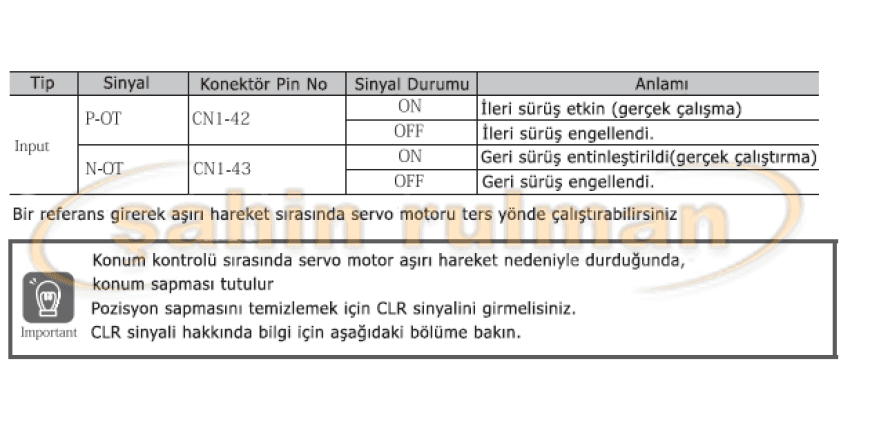
Excessive movement signals include P-OT (Forward Drive Prohibit) and N-OT (Reverse Drive Prohibit) signals.
Use the P-OT and N-OT signals to stop the machine by setting the limit switch. The positions at which you want to stop the machine driven by the servo motor are given in the following servo cable connection example.

Extreme Movement Signals
Excessive motion signals include P-OT and N-OT signals.

Enable/Disable Overdrive Setting

Servo Motor Brake Holding
Brake holding is used to maintain the position of the machine’s moving part when the servo motor is turned off, so that the moving part does not move due to gravity or an external force.
You can use the brakes on the servo motor or provide brakes. The holding brake is used in the following situations.

Brake Operation Sequence
You should consider the time required for the brakes to release and the time required for the brakes to stop in order to determine the time required for the brakes to release and the brake operation timing as described below.

/BK (Brake) Signal

Servo Motor Stop /BK (Brake) Signal Output Timing
When the servo motor is stopped, the /BK signal turns OFF at the same time as the /S-ON signal returns to the OFF position. To change the timing for shutting off the power supply to the motor after the /S-ON signal goes OFF, you should use the servo motor OFF delay time (Pn506).

Servo Motor Operation /BK (Brake) Signal Output Timing
If an alarm occurs while the servo motor is running, the servo motor will stop itself and start the /BK (Brake) signal output by setting the brake reference output speed level. (Rotary servo motors: Pn507, Linear servo motors: Pn583) and Ending the servo motor shutdown brake command waiting time. (Pn508)

Stopping Method for Closed Servo Motor

Electronic Gear Settings
The minimum unit of position data used to carry a load is called the reference unit. The reference unit is used to provide movement quantities, not impacts, which are easier to understand over long distances or in other physical units (e.g., y̅̅m or 0).
The electronic gear is used to convert the movement distances specified in the reference units into the impacts required for actual movements.
The movement distance of the workpiece per reference pulse input is equal to the reference unit servo package with an electronic gear. In other words, if you use the servo package electronic gear wheel, the pulses can be read as reference units.
Note 1: If you install an electronic gear on the main machine controller, normally set the electronic gear ratio in the servo package to 1:1.
Note 2: If you enable the reference pulse input multiplication switching, the reference unit is defined as position data equal to n times the reference pulses entered from the main controller. (“n” is the reference pulse input multiplier.)
The difference between using and not using an electronic gearbox is shown below.
Absolute Servo Motor
In this example, the following machine configuration is used to move the workpiece 10 mm.

Electronic Gear Ratio Settings
Adjust the electronic gear ratio using Pn20E and Pn210.

Electronic Gear Ratio Adjustment Examples
This section provides examples of electronic gear adjustments.

Resetting the Absolute Encoder
In a system using an absolute encoder, various data must be reset at the start. If an alarm related to the absolute encoder (A.810 or A.820) occurs, the absolute encoder must be reset. For example, when the power supply is in the ON position. When you reset the absolute encoder, the multi-track data is reset and alarms related to the absolute encoder are cleared. Reset the absolute encoder in the following situations. When starting the system for the first time
When the A.810 (Encoder Backup Alarm) alarm is generated When the A.820 (Encoder Checksum Alarm) alarm is generated When you want to reset the multi-turn data in the absolute encoder WARNING!
When the absolute encoder is reset, multi-turn data is reset to a value between -2 and +2 revolutions. The reference position of the machine system changes. Set the reference position on the main machine control device to the position resulting from the absolute encoder being reset. If the machine is started without setting the position on the main machine controller, unexpected operation may cause personal injury or damage to the machine.
INFORMATION
In the following cases, multi-valued data will always be zero. In such cases, it is absolutely not necessary to reset the absolute encoder.

Reset Measures
You cannot use the /ALM-RST (Alarm Reset) signal from the servo box to clear the A.810 (Encoder Backup Alarm) alarm or the A.820 (Encoder Checksum Alarm) alarm. You can use the absolute encoder operation to clear these alarms.
If an A.8** occurs, turn off the power supply to reset the alarm.
Preparations
Before performing an absolute encoder reset, you should always check the following.
Parameter writing should not be prohibited.
The servo should not be closed.
Applicable Tools

We have shared with you the basic functions that need to be performed before operating a servo motor. If you encounter any problems during adjustments, you can get support from Şahin Rulman. You can find out the prices of servo motors online and purchase them via the Şahin Rulman website.
Are you looking to select a motor for your disinfectant

Brushless DC motors are called stepper motors. These brushless motors
Many questions are asked about the important considerations regarding driver

Position Control Mode in Servo Motors Servo Motor, In position

Differences Between Unipolar and Bipolar Stepper Motors Unipolar stepper motors