Dezenfektan dolum makinası için motor seçimi yapmak mı istiyorsunuz? Dolum

Stepper motors are motors that rotate in certain steps and provide precise positioning. In order for them to work correctly, the winding leads must be correctly identified. Winding leads are the outputs of the motor’s coils and usually have a multi-wire structure. In case of incorrect connection, the motor will either not run at all or will move erratically.
In order to use stepper motors correctly, the cable structure must be well understood. Stepper motors have electromechanical structures consisting of coils and a large number of cables connected to these coils. Each of these wires represents a specific coil lead or common lead within the motor. Depending on the motor structure, the number and distribution of these cables may vary.
Usually stepper motors have 5 or 6 cables. Fixing these cables in an orderly manner ensures the correct operation of the motor. Details such as the connection sequence between the cables and the common end are critical elements that determine the correct rotation and sensitivity of the stepper motor.
Stepper motors are generally of two types, 5-wire or 6-wire. 5-wire stepper motors have a single common lead in addition to the four wires connected to the coils. This common lead is connected to a single point coming from the center of all coils and is usually connected to the positive end of the source.
In 6-wire stepper motors, the coils are divided into two groups and each group has a separate common lead. In this case, the two common ends represent the center point of the coils belonging to different groups. 6-wire stepper motors are mostly preferred in precision applications.
The common lead is the wire where the stepper motor coils are bundled together and the supply voltage is applied. It is a reference point for the stepper motor and ensures that the motor is correctly energized. If incorrect voltage is applied to the common lead or if these leads are not detected, the motor will not start or rotate properly.
The common terminal also ensures that the voltage difference between the coils is distributed correctly. The controlled and stable stepping of stepper motors depends on the correct determination of the common terminal.
One of the most basic methods to find the stepper motor winding leads is resistance measurement with an ohmmeter. In this method, the resistance values between the motor cables are measured and those that are equal to each other are determined. The common point between cables with the same resistance value refers to the common end.
Another method is the trial-and-error method. In this method, energy is applied to the cables respectively and it is observed how the motor reacts. However, this method is not a professional method and the motor may be damaged in case of incorrect connection.
When measuring the resistance between the stepper motor cables using an ohmmeter, the device is set to the ohm stage. First, the resistance between any two cables is measured and this process is repeated for all cable combinations. The measurement results are compared to find the common end.
In general, the resistances between the common end and the other wires are of the same value. If the resistance between two wires is higher than the others, these wires are the two ends of the coil and not the common end.
Stepper motors with 5 wires have only one common lead. Measurements with an ohmmeter examine the resistances between four different wires. Each wire is measured with the others and the wire that gives the same resistance value as all the wires is determined as the common lead.
While a constant positive voltage is applied to this common end, the remaining four wires are connected to the ground respectively and the motor is stepped. Choosing the wrong cable can cause the motor to vibrate or not turn at all.
In 6-wire stepper motors, the coils are in two groups and each group has a separate common lead. First, the cables are divided into groups and the resistance is measured within each group. In the measurements made between three cables in the same group, the cable that gives equal resistance value is the common end.
After determining the common end in both groups separately, these cables are connected to positive voltage. The other coil leads are energized sequentially with the ground potential and the motor is moved.
Equal values in resistance measurements indicate that the cables belong to the same coil group. For example, two wires measuring 119 Ohms are the ends of a common coil. However, the resistance measured between the outer ends, such as yellow and gray, may be higher.
Depending on the model and construction of the motor, these resistance values may vary. Therefore, specific measurements must be made for each stepper motor.
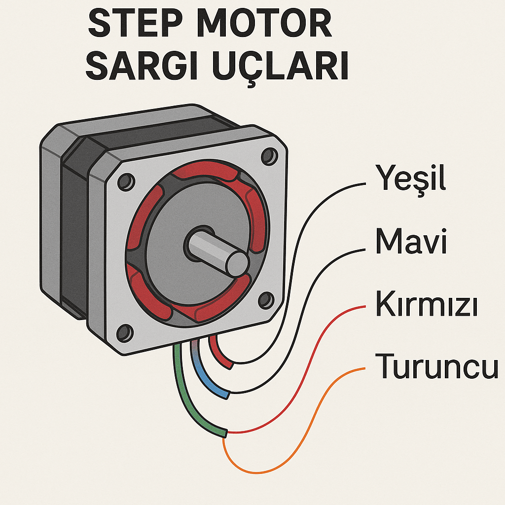
Stepper motor cables usually have specific color codes. These colors may vary depending on the motor manufacturer, but cables belonging to the same group may have similar shades of color. For example, one group may be yellow, gray, red; another group may be blue, green, white, etc.
By looking at these color codes, it can be guessed which cables are connected to each other. However, it is absolutely necessary to measure the resistance for precise information.
For the stepper motor to work correctly, the coil leads must be energized in the correct order. This sequence is usually determined by trial and error. The wrong sequence causes the motor to vibrate or remain stationary, while the correct sequence results in a smooth stepping motion.
Incorrect cable connection will cause the stepper motor not to work properly. In such faulty connections, the motor only vibrates but cannot perform rotational movement. In some cases, the motor does not react at all and becomes inoperable. Incorrect connections can overload the motor coils with excessive current, which can cause the coils to overheat and burn out. Prolonged misuse can render the stepper motor completely unusable.
Incorrectly connected cables can also cause malfunctions in the motor driver. If the motor driver cannot energize the coils in the correct sequence, it will overload and the drive circuit may be damaged. This causes damage not only to the motor but also to the control circuitry. Incorrect wiring can result in system-wide performance degradation, sudden stops or faulty duty cycles.
In order for the stepper motor to work properly, the common end must be correctly identified and connected to a constant positive voltage. Usually this voltage varies between 5V and 12V. Chassis potential is applied sequentially to the coil terminals. This sequence allows the motor to rotate clockwise or counterclockwise. Thanks to the correct connection, the motor runs stably and without vibration.
The cable sequence can be found by testing step by step. First, a positive voltage is applied to the common terminals and the coil terminals are sequentially grounded. The response of the motor is checked at each step. When the motor shows smooth stepping motion, the sequence is verified.
The common lead is the reference voltage source of the stepper motor. It is usually connected to the positive pole of the source and this voltage is kept constant. The voltage value should be chosen according to the operating characteristics of the motor. Too low voltage may cause the motor not to rotate and too high voltage may cause the coils to overheat.
Chassis potential is applied to the coil ends in the correct sequence. This sequence ensures that the motor operates in a healthy and directionally controlled manner. If the sequence is incorrect, the motor either does not rotate or rotates in the wrong direction. This sequence is of great importance for the precise stepping motion of the stepper motor.
Thanks to this sequencing logic, the direction of the stepper motor can be easily changed and precise movements can be achieved.
One of the most common mistakes in stepper motor connections is to determine the common end incorrectly. A wrongly determined common lead causes the motor not to start. In addition, when the sequence between the coil leads is mixed up, the motor either vibrates or does not rotate at all. Using wrong voltage values also shortens the life of the stepper motor.
Correct applications always start with resistance measurement. After the common end is correctly determined, the cable sequence should be carefully determined and the voltage values should be selected according to the motor characteristics. In this way, the stepper motor works long-lasting and efficient.
Correct common lead and coil sequence determination is critical for efficient and trouble-free operation of the stepper motor. When these determinations are made correctly, the stepper motor takes precise and controlled steps. Incorrectly detected cable connections can cause serious malfunctions for both the motor and the stepper motor driver circuit. Therefore, measurement and connection processes should be carried out carefully.
Dezenfektan dolum makinası için motor seçimi yapmak mı istiyorsunuz? Dolum

Fırçasız doğru akım motorlarına step motor denir. Fırçasız olan bu
Servo Motor Kontrolü Nasıl Yapılır? Bu haftaki blog yazımızda servo
Step motorlar için sürücü seçimi ve jumper ayarları ile ilgili

Servo Motorlarda Pozisyon Kontrol Modu Servo Motor, Pozisyon kontol modunda titreme

Unipolar ve Bipolar Step Motor Arasındaki Farklar Unipolar step motor