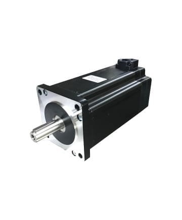


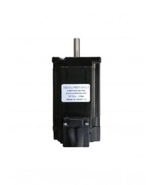
Encoder cable Step Motor 86BHH150-600-40Mp
SKU: 86BHH150-600-40Mp| ENCODER STEPPER MOTOR TECHNICAL SPECIFICATIONS | |
| Maximum Torque | 16.0 Nm |
| Holding Torque | 8.6 Nm |
| Current | 6.0 Amper |
| Flange Size | 86×86 mm |
$125,00
Encoder cable Step Motor 86BHH150
Encoder glide Step Motor Maximum Tork: 16.0 NM
Stepper Motor Holding Torque with Encoder: 8.6 NM
Stepper Motor Current with Encoder: 6.0 Amps
Stepper Motor Flange with Encoder: 86X86 mm
Encoder cable Step Motor Boy: 167 mm
Stepper Motor Cable with Encoder: 4 pcs
Stepper Motor with Encoder Product Code: Stepper Motor with Encoder 86BHH150-600-40Mp

Stepper Motor Connecting Settings with Encoder
BLUE: A+
YELLOW: A-
BLACK: B+
RED: B-
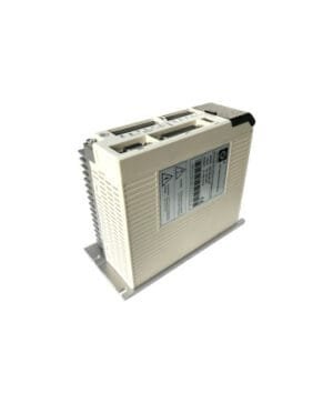
The most feared step miss in stepper motors is solved by using a closed loop system in this series. The 1000 pulse encoder disk and reader behind the motor informs the driver whether the motor is taking the steps it should take or not. The driver boosts the motor by increasing the amperage for the steps it cannot take. If there is still a step it cannot take, it stops by turning on the alarm. It is preferred because it can respond much faster (close to servo) to sudden stop-start compared to stepper motors, and the position is guaranteed by monitoring the alarm output.
Compensates for missed pulse (backup). It returns to the missed position. In addition, since the holding torque has a locking feature like stepper motors, they are the leading systems in position protection.
It does not require position tracking by following the encoder output. It is our experience so far that it is in full position as long as there is no alarm.
IMPORTANT REMINDERS
Drive Jumper settings must be made with the drive switched off for safety.
The metal part of the panel where the drives are located must be grounded. (The need for grounding can be understood by connecting a voltage measuring device to the neutral and ground cables.)
In PLC, Arduino, Axis control card or specially designed cards, PULSE and DIR signals must be sent as 5V.
If the PULSE and DIR signals to be distributed individually in negative (NPN) or positive (PNP) driving are above 5 volts, a resistor must be entered. Example 1.8KΩ for 24Volt.
Encoder Cable Pin numbers
|
Color of the wire |
function |
|
|
3pin |
white |
EGND |
|
2pin |
red |
VCC |
|
13pin |
blue |
EA- |
|
1pin |
black |
EA+ |
|
12pin |
green |
EB- |
|
11pin |
yellow |
EB+ |
Based on 0 reviews
Be the first to review “Encoder cable Step Motor 86BHH150-600-40Mp”
You must be logged in to post a review.


There are no reviews yet.