İçindekiler

Making the Cable Connections of the Servo Motor

Servo Motor Noise Filter

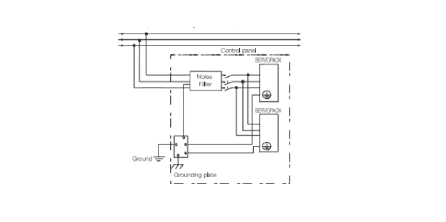
A noise filter must be installed to protect the servo motor from external noise and sound. The noise filter is installed on the servo motor as follows.

The following precautions must be taken when installing a noise filter on a servo motor.

  • You must separate the input lines from the output lines. You need to connect these channels through separate channels.
    • You must separate the grounding cables of the audio filter from the output lines.
      • Connect the ground wire of the audio filter to the grounding plate and do not connect the ground wire to other ground wires.


      Sound filter grounding
      Servo Motor Basic Connection Diagram

      Servo Motor Power Supply Connection

      Terminal Symbols and Terminal Names

      Encoder Connector Pin Assignment (CN4)

      Connecting the Servo Motor Braking System An example of the brake cable holding the servo motor is shown in the image below.

      Servo Motor Signal ConnectionsI/O Signal Connections (CN3) Names and Functions You can review the default I/O signal settings by pin number, name, and function in the table below. Input Signals *Default settings are indicated in parentheses.
      Output Signals
      Signal Wiring Examples Servo Motor Signal Wiring Speed Control Example

      Servo Motor Signal Wiring Position Control Example


      Servo Motor Signal Wiring Torque Control Example

      CircuitsReference Input Circuits
      Analog Input Circuits
      This section describes the CN3 connector terminals. 1-16 (Speed Reference Input) and 2-17 (Torque Reference Value)
      Analog signals are used as both speed and torque reference signals. The input impedance is as follows.
      • Speed Reference Input: Approximately 14 kΩTorque Reference Input: Approximately 14 kΩ

      *Maximum voltage allowed for input signals ± 10V

      Position Reference Input Circuits This section describes CN3 connector terminals 19-4 (Reference Pulse Input), 18-3 (Reference Signal Input), and 40-24 (Open Input).
      Series Input CircuitsPhotocoupler Input Circuits The circuits are connected via relay or open-collector transistor circuits. You should use a low-current relay. Otherwise, a fault contact may occur in the servo motor.
      Photocoupler output circuits are used for ALM (Servo Alarm) series output circuits, and for other /S-RDY (Servo Ready) series outputs. Connect the photocoupler output circuits to a relay or line receiver circuits.

      Line Driver Output CircuitsIn this section, the CN3 connector pins should be connected as follows: 10-11 (phase-a signal), 12-13 (phase-b signal), 14-15 (phase-c signal).
      For detailed information about servo motor cable connections and to purchase servo motors, please contact Şahin Rulman.

Diğer Blog Yazılarımız

Para birimini seçin