Types of Rack Gears
Rack gears are critical mechanical components used to achieve linear motion and are available in different types depending on application requirements. There are generally five main types: Helical Rack Gears, Gear Racks (Straight Tooth Bars), Guided Rack Gears, Curved Rack Gears, and Helical (Spiral) Rack Gears. A closer look at these types:
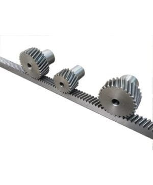
Helical Rack Gears
Also known as helical rack gears, these are designed to convert motion between linear movement and gear systems. Unlike standard racks, they feature angled (helical) teeth. This design enables quieter and smoother operation, better load distribution, and reduced friction between teeth. Helical racks are typically preferred in applications requiring high precision and strong performance, offering long-lasting and reliable operation.
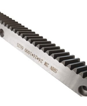
Gear Racks (Toothed Bars)
Gear racks are used in mechanical systems to provide linear motion by interacting with gear wheels. They convert rotational motion into linear motion and are typically manufactured from metal or plastic. These components ensure precise and reliable motion control and are widely used in CNC machines, robotic systems, and automation applications.
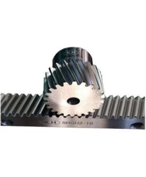
Guided Rack Gears
Guided rack gears are a type of rack used together with a gear bar to convert rotational motion into linear motion. Their main advantage is the guiding surfaces integrated into the design. These surfaces improve movement stability and accuracy, enabling systems to operate with less friction and higher precision.
Curved Rack Gears
Curved rack gears have a bent or curved structure compared to standard straight racks. This design allows precise linear motion along curved paths or surfaces. They are ideal for machines or systems with complex geometries and are commonly used in defense industries and specialized industrial machinery.
Helical (Spiral) Rack Gears
Helical rack gears feature teeth cut at an angle along the rack. This increases the contact area between gears, allowing higher load capacity and quieter operation, while also providing smoother motion.
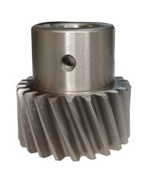
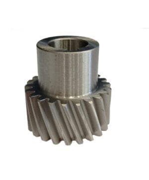
Pinion Gears
Pinion gears are essential components in mechanical systems that convert rotational motion into linear motion. They are typically used together with rack gears to form linear motion mechanisms.
Rack Gear Dimensions
Rack gear dimensions are crucial for proper system operation, full compatibility with the pinion, and long service life. These dimensions are determined based on load capacity, motion precision, and operating speed, and are usually expressed in millimeters.
The most fundamental parameter is the gear module (m), which defines the size of the teeth and must match the pinion gear exactly. Incorrect module selection can cause wear and vibration during operation.
Tooth pitch refers to the distance between teeth on the rack and directly affects motion precision. Smaller pitches provide higher precision, while larger pitches allow greater load capacity.
Tooth height and depth determine engagement strength and affect durability and load behavior by influencing the contact surface between rack and pinion.
Pressure angle indicates the angle of tooth contact and is typically manufactured in standard values such as 14.5°, 20°, or 25°. The most common value is 20°, offering a good balance between strength and quiet operation.
Additionally, rack length is determined based on the application and can be customized. Travel distance and mounting space must be considered when selecting the length.
Choosing the correct rack gear dimensions improves system performance, reduces maintenance needs, and ensures smooth operation with the pinion. Therefore, technical requirements and operating conditions should always be carefully evaluated.
Applications of Rack and Pinion Systems
Rack and pinion systems are widely used in many industries where rotational motion must be converted into precise and controlled linear motion. Their high load capacity, positioning accuracy, and durability make them suitable for both industrial and commercial applications.
In the automotive sector, these systems are commonly used in steering mechanisms, converting the rotation of the steering wheel into controlled linear motion for the wheels, improving driving comfort and maneuverability.
In industrial machinery and production facilities, rack and pinion systems are used in CNC machines, presses, and automation lines to provide linear axis movement, ensuring stable and repeatable motion in precision manufacturing processes.
In robotics and automation, they enable accurate positioning of robotic arms and linear modules, especially in high-speed and high-precision applications.
In the construction and steel structure industry, they are used in cranes, lifting systems, and heavy load equipment to safely move large loads linearly.
In elevator systems and moving platforms, they provide smooth and controlled vertical motion, enhancing both safety and comfort.
In agricultural machinery, rack and pinion systems are used in mechanisms requiring precise motion, such as planting, harvesting, and adjustment systems, ensuring efficient and reliable operation.
Helical Gear Calculation in Rack Systems
Helical gear calculation in rack systems is a critical engineering process that directly affects load capacity, noise level, and motion precision. Thanks to the helical tooth structure, teeth engage gradually, reducing vibration and distributing loads more evenly. Therefore, not only dimensions but also operating conditions must be considered during calculations.
The primary parameter is the gear module (m), which determines tooth size and is directly related to load capacity. The helix angle (β) defines the inclination of the teeth relative to the axis. As this angle increases, the contact surface also increases, resulting in quieter operation and higher load capacity. However, larger helix angles also generate higher axial forces, so bearing and mounting design must be adapted accordingly.