| No |
Error Name |
Definition |
No |
Error Name |
Definition |
| — |
Normal |
|
29 |
Alarm for torque overload |
Motor load exceeds user-set values and range |
| 1 |
Excessive Speed |
Motor speed is above the set values. |
38 |
Encoder EEPROM communication read or write error |
Encoder cable not connected Or encoder interface circuit fault |
| 2 |
Main circuit overvoltage |
Main circuit voltage too high |
39 |
Data CRC check error |
The motor encoder wrote no data and all 0. |
| 3 |
Main circuit low voltage |
Main circuit voltage too low |
40 |
Model not supported |
The drive does not support this motor model |
| 4 |
Position overshoot |
The value of the position deviation counter is above the set value. |
41 |
You need to change the engine model |
Current motor inconsistent with selected drive model |
| 5 |
Overheating of the drive |
High temperature of the driver |
42 |
AC input low voltage |
AC input low voltage |
| 6 |
Speed booster saturation error |
Speed adjustment for long-lasting saturation |
47 |
Overvoltage in main circuit |
Over-voltage when opening the main circuit |
| 7 |
Driver blocking error |
Speed adjustment at saturation for a long time |
50 |
Encoder communication error |
Driver and encoder not connected |
| 8 |
Position deviation accumulation was out of range |
The absolute value of the position deviation accumulation is above 2 30 |
51 |
Encoder communication abnormal |
After the encoder establishes communication, interruption and disconnection appear. |
| 11 |
IPM module error |
IPM smart module error |
52 |
Encoder battery voltage insufficient alarm |
Encoder battery voltage insufficient alarm, but the information is not lost and needs to be replaced as soon as possible |
| 13 |
Drive overload |
Servo drive and motor overload (instantaneous overheating) |
53 |
Encoder battery voltage error alarm |
Encoder battery voltage error alarm and storage information, an error occurred requiring the encoder to be reset. |
| 14 |
Brake problem |
Brake circuit Fault |
54 |
Encoder error alarm |
The encoder alarm without battery, but you need to reset the encoder again. |
| 18 |
Relay switch fault |
The actual state of the relay is different from the control state. |
55 |
CRC check fails 3 times in a row |
Encoder communication received data CRC verification 3 consecutive errors. |
| 19 |
Error occurred when there was a delay to open the brake |
Impact inputs before opening |
56 |
MODBUS frame too long |
MODBUS frame data received is too long |
| 20 |
EEPROM error |
EEPROM error |
57 |
Abnormal MODBUS communication format |
Incorrect setting of communication parameters or incorrect address or value |
| 21 |
FPGA module error |
FPGA module error |
58 |
Single turn position error |
Single rotation position offset stored by the drive exceeds encoder resolution |
| 23 |
Current collection circuit malfunction |
Current collection circuit malfunction |
59 |
Encoder reports CF error |
The encoder constantly reports CF domain error and you need to reset the encoder |
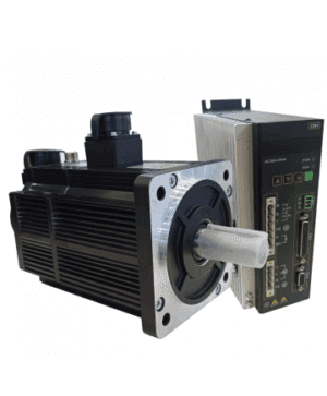
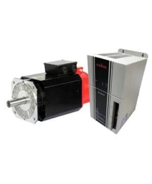 Spindle Servo Motor 11 kW
1 × $2.100,00
Spindle Servo Motor 11 kW
1 × $2.100,00 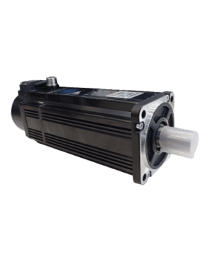 Servo Motor with Brake 1000 Watt
1 × $330,00
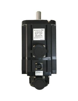
Servo Motor with Brake 1000 Watt
1 × $330,00 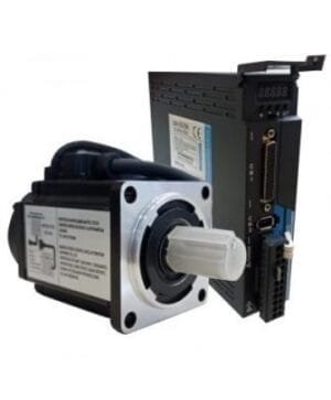 Servo Motor with Brake 400 Watt
1 × $225,00
Servo Motor with Brake 400 Watt
1 × $225,00 

There are no reviews yet.